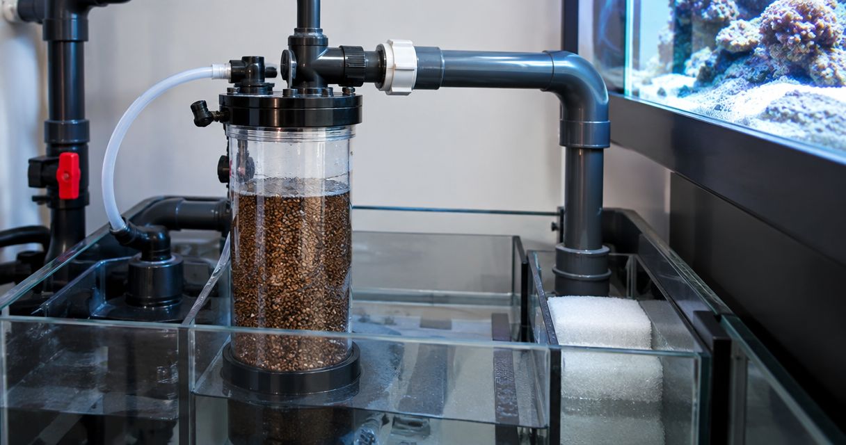
Instead of repeatedly adjusting a separate reactor pump, connect your GFO reactor to the sump return line through a separately valved branch, then discharge the reactor outlet back into the sump. Keep the main return path open: the reactor receives a controlled share of flow, never the full display return.
- Krakking Korals’ GFO reactor sump return line guide suits reef keepers adding a controlled phosphate-removal branch.
- Install a tee after the return pump, with an independent valve before the reactor inlet.
- Keep display return flow separate from reactor flow; follow the reactor and phosphate media instructions.
- Verify leaks, drain-back, media movement and phosphate response before leaving the setup unattended.
Why this matters
A GFO reactor holds granular ferric oxide media that adsorbs phosphate from aquarium water. The plumbing needs to deliver enough flow through the media without grinding it or carrying particles into the reef.
For a 2026 reef plumbing upgrade, start with the media instructions rather than a universal flow-rate target. If you use Rowaphos Phosphate Remover, check its preparation and operating instructions before loading the reactor. Different phosphate-removal media do not share identical handling requirements.
Krakking Korals’ GFO reactor plumbing guide is best for reef keepers adding phosphate removal to an existing sump return. A manifold removes the need for a dedicated feed pump, but it also ties reactor flow to the return pump’s operating state.
Before you start
- Confirm compatibility. Have the reactor manual, media instructions, return pump information and access to the pressure-side plumbing. Check the reactor’s permitted pressure, connection sizes and mounting requirements before choosing fittings.
- Gather suitable materials. Use aquarium-compatible pressure plumbing, a tee, an independent branch valve, service disconnects, compatible adapters and secured tubing. Keep a bucket, towels, replacement saltwater and a phosphate test ready.
- Pre-empt the return-flow gotcha. Opening a reactor branch changes the return pump’s operating point and can alter display flow. Record the normal overflow behaviour and sump operating level before modifying anything; isolate automatic top-off during commissioning.
Check thread standards as well as nominal sizes. A fitting labelled 1/2 inch NPT is not automatically compatible with an Australian plumbing fitting carrying a similar size label. Likewise, 1/4 inch RO tubing and dosing tubing labelled 3 mm ID and 5 mm OD are not interchangeable just because both look narrow.
Those labels describe different connection or tubing dimensions, not reactor recommendations. Choose tubing from the reactor’s connection requirements, not from whatever is already in the cabinet.
Choose the feed arrangement
A return-line branch is useful when the existing pump and plumbing can support the added load. A separate feed pump is the adjacent workflow when independent operation matters more than reducing equipment.
| Arrangement | Best for | Advantage | Limitation |
|---|---|---|---|
| Valved return branch | Sumps with accessible return plumbing and sufficient pump capacity | Uses the existing return pump; provides a serviceable reactor feed | Reactor flow changes when return settings change |
| Separate feed pump | Systems needing reactor operation independent of the return | Separates reactor adjustment from display return adjustment | Adds another pump to clean and another powered component |
Neither arrangement fixes excessive media loading or unsuitable flow. Krakking Korals’ reef equipment guidance starts with the same rule for both: establish stable circulation, then adjust phosphate removal separately.
Do not proceed with a return branch if the reactor’s pressure suitability is unclear. Keep it disconnected until you have confirmed the operating requirements.
Return branch layout
- Map the water paths. Trace the return pump discharge to the display. Place the proposed tee on this pressure-side route, with the main run continuing towards the display and the side branch feeding the reactor.
- Plan independent control. Put the reactor feed valve on the branch before the reactor inlet. Do not use the main display return valve to regulate media movement.
- Plan service access. Position disconnects so you can remove the reactor without cutting pipe. Leave room to lift the lid and handle wet media without touching electrical equipment.
- Choose the outlet location. Return reactor effluent to a sump location where it will mix with system water. Secure the outlet above the normal water surface where practical to create an air break, while keeping splashing contained.
There are 2 water paths after the tee: the display return and the reactor branch. Water leaving the reactor goes back to the sump, not through a sealed connection into the pressurised display return.
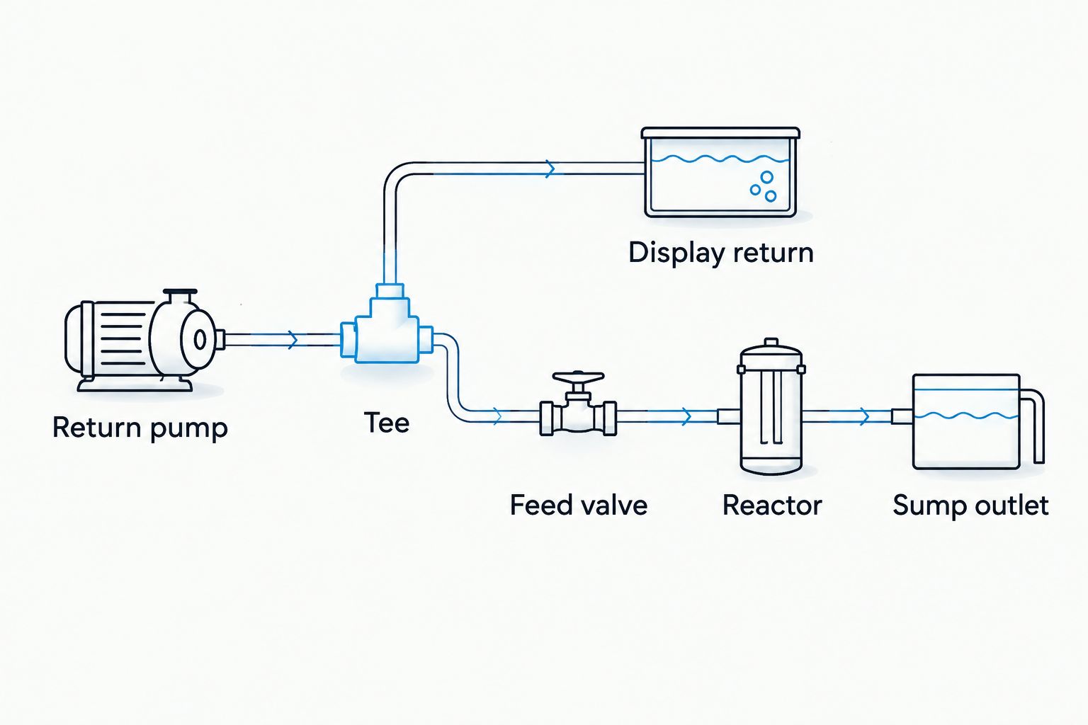
Expected result: you can trace the reactor feed, isolate it, and identify where its discharge returns without interrupting the main return route.
Plumbing assembly
- Stop and isolate equipment. Switch off the return pump and affected equipment before disconnecting plumbing. Let the display drain back, then confirm the sump can contain the water before removing fittings.
- Dry-fit the branch. Check alignment, pipe support, valve access and reactor clearance. Avoid using the reactor ports to support the weight of rigid pipe.
- Make compatible joints. Follow the fitting manufacturer’s instructions for solvent-welded, threaded, compression or hose connections. Allow solvent joints their specified cure time before exposure to aquarium water.
- Add service disconnects. A Grey DIN Union is an example of a service fitting; select the correct size and connection standard for your actual pipework. Do not assume any union fits an existing installation.
- Secure flexible connections. Use the reactor manufacturer’s specified fittings and suitable clamps where required. Prevent kinks, sharp bends and tubing contact with hot equipment.
Keep the branch valve closed for the first restart. Inspect the assembled feed under normal return-pump operation before admitting water to the reactor.
Expected result: the display return operates with the reactor branch isolated, and the new joints remain dry. Add the pipe sizes, thread standards and joint cure details to your 2026 maintenance record so future replacement fittings match.
Media loading and flow adjustment
- Establish a phosphate baseline. Test aquarium water before starting the reactor. Record the result alongside the media type and amount used; follow the media instructions for loading rather than filling the chamber by eye.
- Prepare the media correctly. Follow the specific rinsing or initial flushing procedure. Do not apply another product’s preparation method to the media in your reactor.
- Check internal assembly. Fit the supplied screens, sponges and internal parts in the order shown in the reactor manual. Keep particles away from the lid seal and inspect the seal before tightening.
- Open the feed gradually. Admit water slowly and purge trapped air according to the reactor instructions. Where initial effluent must be discarded, collect it in a bucket and watch the sump level continuously.
- Set media movement. For media intended to fluidise, aim for the movement described by its manufacturer, not vigorous boiling. Stop and reduce flow if particles rise towards the outlet or the bed churns aggressively.
Replace discarded saltwater with matched saltwater; do not let automatic top-off replace it with freshwater. Keep the return pump submerged throughout flushing.
Expected result: the reactor is full, the outlet is secure, and water passes through the media without carrying particles into the sump.
Restart and shutdown verification
- Inspect operating conditions. With the branch open, check joints, reactor seals, outlet stability and display overflow behaviour. Adjust the branch valve before changing the return pump setting.
- Check display return performance. Confirm the display still receives suitable return flow. If you change pump speed, check reactor movement again because the feed pressure has changed.
- Simulate a shutdown. Turn the return pump off while watching the sump. Confirm the combined display and reactor drain-back stays within the sump’s free capacity; never rely on a check valve as the only flood protection.
- Restart under observation. Restore the normal pump setting and confirm the reactor clears air, resumes its intended flow and does not leak. Recheck any controller start-up or feed-mode behaviour you actually use.
- Restore top-off. Once normal levels are stable, return automatic top-off to service and confirm its sensor position still suits the operating water level.
Complete 2 operating checks: pump running and pump stopped. A dry cabinet during normal operation does not prove that the sump can handle shutdown drain-back.
Expected result: your 2026 commissioning record confirms stable running, contained drain-back and a repeatable restart. Do not leave the system unattended before those checks pass.
Reconnect after a media change
The second workflow is servicing the reactor while keeping the main return running. Use it only when the branch can be isolated safely and the reactor’s service procedure allows it.
- Close the reactor feed valve and disconnect power to any associated equipment as required.
- Relieve trapped pressure using the reactor manufacturer’s procedure. Catch retained water before loosening service fittings; account for any submerged outlet that can siphon.
- Remove spent media and clean the internal screens and distribution components according to the manual.
- Inspect the seal, reload the specified media amount and reconnect the reactor.
- Repeat the preparation, gradual restart and leak checks. Recheck media movement rather than reopening the valve blindly to its previous position.
Expected result: the display return stays stable throughout servicing, and the reactor returns to controlled operation without releasing media dust into the system. Record each media change in the same 2026 log as your phosphate results.
Troubleshooting
The media boils or escapes
Close the branch valve enough to stop aggressive movement, then inspect the internal screens and media loading. Confirm the media is suitable for the reactor. Increasing flow is not a substitute for correcting a poorly assembled chamber.
The media bed barely moves
Check the valve position, tubing bends, inlet blockage and dirty screens before increasing pump speed. Some media are not intended to tumble; use the product instructions to decide whether the observed movement is actually a fault.
Display flow drops after opening the branch
Reduce branch flow and reassess the display return. If both paths cannot operate satisfactorily within the pump’s permitted range, use the separate-feed arrangement rather than forcing a compromise through the main return valve.
Water leaks around the reactor lid
Isolate the branch, relieve pressure and inspect the seal for trapped granules, damage or incorrect seating. Confirm the reactor is operating within its specified limits. Do not keep tightening a leaking lid under pressure.
Phosphate falls faster than intended
Confirm the reading using the test instructions, then reduce or pause phosphate removal. Review media loading and the aquarium’s nutrient trend before restarting. Do not chase an undetectable reading simply because the reactor can produce one.
Customise your workflow
Make maintenance access the next improvement, not another branch by default. Label the reactor feed valve, keep its service space clear and retain a plumbing sketch showing which fittings isolate which equipment.
For a 2026 maintenance routine, check reactor flow whenever you clean the return pump, change its speed or service another manifold branch. Those changes affect the shared hydraulic system even when the reactor itself has not been touched.
Pair those checks with phosphate testing and coral observation. The Krakking Korals GFO reactor workflow treats plumbing stability and nutrient response as separate checks: a reactor can run neatly while removing more phosphate than your reef needs.
FAQ
Can I connect a GFO reactor directly to my sump return line?
Yes, through a separately valved branch after the return pump, provided the reactor is suitable for the operating pressure. Keep the main display return separate and send reactor effluent back to the sump.
Should the whole return flow pass through a GFO reactor?
No, the reactor should receive a controlled branch flow rather than the full display return. Its media-flow requirements must not dictate the aquarium’s main return circulation.
Where should the GFO reactor outlet go?
Secure the outlet in the sump where its discharge mixes with system water. An outlet above the normal water surface provides an air break, but you must still verify shutdown drain-back and contain splashing.
How much flow does a GFO reactor need?
Use the reactor and media manufacturers’ instructions rather than a universal flow rate. Adjust the branch gradually and avoid grinding the media or carrying particles into the outlet.
Is a manifold better than a separate reactor pump?
A manifold suits systems with accessible plumbing and sufficient return-pump capacity; a separate pump suits systems needing independent reactor operation. The manifold removes a dedicated feed pump but ties reactor flow to return-pump changes.
Do I need to rinse GFO before using it?
Follow the preparation instructions for the exact media you use. Rinsing and initial flushing requirements differ, and discarded saltwater must be replaced with matched saltwater rather than freshwater top-off.
Can I change reactor media without stopping the return pump?
Yes, if the reactor branch has safe isolation and the reactor’s service instructions allow it. Close the feed, relieve pressure and account for retained water or outlet siphoning before disconnecting anything.
Why does my reactor flow change after pump cleaning?
Cleaning the return pump changes the shared system’s flow conditions, so the reactor branch needs checking again. Reconfirm media movement and display return behaviour before leaving the equipment unattended.
One last thing
A valve position is not a flow measurement. Marking the handle helps you return to a starting point, but pump cleaning, dirty media screens and changed return settings can all change the flow at that same position.
After every intervention, watch the media and check the display return. That small habit catches a problem a neat plumbing layout cannot show.